
 Product Catalog
22.07.25
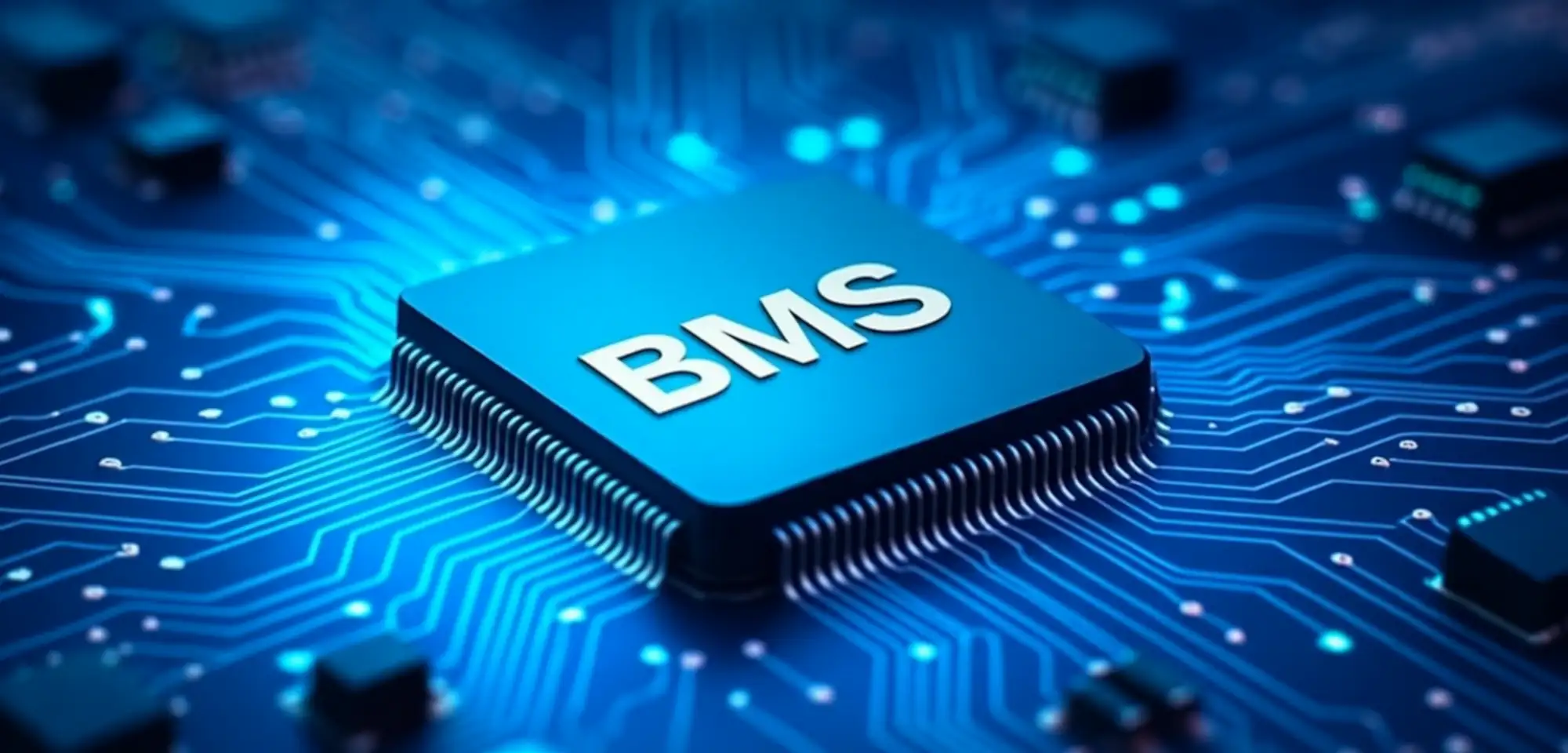
A BMS manages all battery system parameters: voltage, current, temperature, and capacity — maintaining efficiency and preventing failures
Why Does a Battery Pack Need a BMS?
In today's energy systems — electric vehicles, solar stations, FPV drones, portable devices — lithium batteries have become the main power source. Their compactness, high energy density, and stability have made these batteries indispensable across dozens of industries.
But despite their technical excellence, lithium packs remain vulnerable to overheating, overvoltage, cell degradation, and thermal runaway. Their safety and performance depend not only on cell quality but also on the ability to manage all system parameters.
This is where the BMS comes into play — a system that controls charging/discharging current, temperature, cell balancing, and the state of the battery resource. It doesn't just monitor; it actively intervenes in battery processes, preventing critical operating modes and extending the lifespan of the entire pack.
A BMS manages all parameters of the battery system: voltage, current, temperature, and capacity, maintaining efficiency and preventing accidents.
Let’s explore how a BMS works, what types exist, how it integrates into packs, and what technical details should be considered when selecting one.
Monitoring That Saves the Pack: BMS Surveillance and Protection
A BMS constantly monitors the critical parameters of the battery system and reacts to any dangerous changes. Monitoring is not passive — every observation results in a protective action that preserves the cell’s lifespan and safety.
What BMS Boards Can Monitor
- Voltage Control
The BMS monitors voltage on each individual cell. If the voltage exceeds the allowable level, overvoltage protection (OVP) activates: charging is halted, and the cell is isolated until stabilization. - Temperature Control
Thermal sensors measure temperature at key battery zones — both on the cells and nearby. Upon detecting overheating, the system instantly responds: over-temperature protection (OTP) triggers, blocking charge/discharge and signaling an alarm. - Charge and Discharge Current
The BMS records current flow during charging and discharging, adjusting it according to settings or external limits. If current exceeds safety thresholds, overcurrent protection (OCP) activates: power MOSFET circuits interrupt current and issue a warning. - State of Charge (SoC)
Charge level is calculated using cumulative methods (coulomb counting) with correction based on open-circuit voltage. This allows the BMS to adapt loads, predict runtime, and avoid deep discharge (UVP), which is harmful to the battery. - State of Health (SoH)
The BMS evaluates internal resistance, capacity loss, and cell behavior under load. These data help identify and replace degraded cells in time and prevent critical failures.
Cell Balancing: Maintaining Energy Symmetry
Even minor imbalances between cells can cause capacity loss or premature shutdown. The BMS automatically equalizes voltage, reducing stress on stronger cells and maintaining uniformity across the battery.
- Passive Balancing
Resistors on balancing channels discharge cells with excessive voltage — simple and effective but results in energy loss as heat. - Active Balancing
Energy is redistributed between cells via inductive or capacitive circuits. This reduces heat loss but requires more complex circuitry. - Balancing Activation Conditions
Depending on the algorithm, balancing activates at a certain charge level or during idle when the system is not under load.
Communication and System Integration
The BMS is not an isolated element. It continuously transmits data to other modules, controllers, or user interfaces.
- Telemetry Transmission: real-time voltage, temperature, SoC/SoH
- Alarm Signals: overvoltage, overheating, degradation
- Threshold Settings and Calibration: via Bluetooth, UART (Universal Asynchronous Receiver/Transmitter), CAN (Controller Area Network)
- Integration: with inverters, charging stations, mobile apps
This creates an adaptive system that not only self-regulates but also seamlessly integrates into larger energy solutions.
| Parameter | Passive Balancing | Active Balancing |
| Operating Principle | Excess energy is discharged through resistors | Energy from "overcharged" cells is transferred to weaker ones |
| Efficiency | Heat losses; slower balancing | Minimal loss, even distribution of charge |
| Complexity | Simple design, fewer components | Complex electronics: controllers, transformers, capacitors |
| Power Consumption | Low in standby, but higher heat generation in use | Optimized, but requires cooling and stabilization |
| Use Case | Budget BMS modules, DIY, small packs | Industrial ESS (Energy Storage Systems), battery cabinets, EVs |
| Pros | Simplicity, affordability, compact size | High precision, effective resource management |
| Cons | Energy loss, unsuitable for high-performance systems | Cost, size, complex firmware and setup |
Extra Option: Some BMS support hybrid modes — passive balancing during charging, and active balancing during idle or optimization.
BMS Classification: How Control Logic Is Built
BMS systems may differ significantly in format, scale, and interaction with cells. Their classification is based on architecture — from monolithic controllers to decentralized modules with high scalability.
Types of BMS Architectures
- Centralized BMS — a single board that manages all battery cells from one location. It receives data from each cell via individual wires, making it suitable for compact packs (up to 8–16S). This format is easy to install but susceptible to electrical noise and less scalable.
- Modular BMS — consists of several blocks, each serving a group of cells. A central controller coordinates all modules via master-slave communication. This ensures accurate measurements, reduces noise, and allows scalability to dozens or hundreds of cells without compromising stability.
- Decentralized BMS — each cell has its own board with a sensor, balancer, and controller. This architecture provides high accuracy, short signal lines, and minimal loss, especially in large systems based on 18650 or 21700 cells. Data is transmitted via UART, I²C, or other buses, making the system flexible and highly scalable.
- Integrated BMS — built directly into the battery housing, simplifying use and minimizing wiring. Suitable for portable devices, but harder to service — replacement is often impossible if the system fails. Mainly used in power banks, power tools, and compact ESS (Energy Storage Systems).
Why FPV Batteries Don’t Use a BMS, But Rely on a Balance Cable
FPV batteries are designed for maximum power and minimum weight. Adding an integrated BMS would result in:
- Increased internal resistance, limiting peak current and causing overheating during sharp aerial acceleration.
- Excessive load on the BMS board: short flight sessions and high charge/discharge cycling require components with lab-proven endurance, which compact BMS modules lack.
- Risk of failure due to mechanical vibration and impact during hard landings, increasing the likelihood of total battery failure.
Instead, a balance cable is used, which:
- Connects to a professional charger that supports balancing.
- Adds no resistance to the flight circuit and introduces no extra failure points during long-term use.
This approach offers the best compromise between safety and performance: by balancing cells before takeoff, the pilot ensures even voltage across the battery without the burden of a BMS inside the drone.
News and Reviews


01/09/2026
Top News for the Morning of September 1, 2026. Russia is using tactics of attrition against Kyiv
BTRY.ENERGY offers news and articles in Ukrainian with a focus on preserving Ukrainian identity, citizens' rights, and t...

31/08/2026
Pentagon: Arsenal to be expanded
BTRY.ENERGY offers news and articles in Ukrainian with a focus on preserving Ukrainian identity, citizens' rights, and t...

31/08/2026
Three major American publications focus on Ukraine. Why does this matter?
BTRY.ENERGY offers news and articles in Ukrainian with a focus on preserving Ukrainian identity, citizens' rights, and t...

31/08/2026
Top News for the Morning of August 31, 2026. The world has finally entered a global conflict
BTRY.ENERGY offers news and articles in Ukrainian with a focus on preserving Ukrainian identity, citizens' rights, and t...

28/08/2026
A new nuclear technology: micro-reactors. Why is this important?
BTRY.ENERGY offers news and articles in Ukrainian with a focus on preserving Ukrainian identity, citizens' rights, and t...
28/08/2026
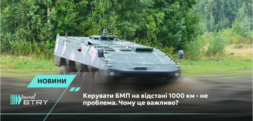
Operating an infantry fighting vehicle (IFV) from a distance of 1,000 km is not a problem. Why is this important?
BTRY.ENERGY offers news and articles in Ukrainian with a focus on preserving Ukrainian identity, citizens' rights, and t...
Consultation
Need more information?
Would you like to learn more about BTRY.ENERGY or get a personal consultation - fill out the form and we will contact you


